Not all 3D models are created equal. The difference between a polygonal model and CAD can bring your work to a crash.
Moving from the segmentation stage to the complementary digital processing, the stage where the model is cleaned, cut, and gets added parts, bases, connectors, magnets, text and color, we meet two completely different languages of models: smooth surfaces (CAD) versus dense triangles (polygonal mesh).
This is part 3 of the series. Part 2: Segmentation for 3D medical models.
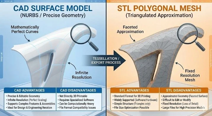
What's the difference? CAD vs polygonal
- CAD (surface / solid models): smooth mathematical surfaces, accurate down to the finest detail, ideal for engineering and design. Advantage: unlimited precision, easy to edit dimensions and combine with mechanical parts. Disadvantage: struggles with the "heavy" polygonal files that come out of segmentation.
- Polygonal mesh: a model built from a network of small triangles (STL, OBJ). Advantage: faithfully represents the data from the scan. Disadvantage: hard to make clean geometric changes on it.
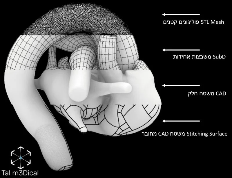
About the image: a visualization of an anatomical heart model that combines 4 types of geometry common in my work:
- Small polygons, STL mesh: a dense triangle structure, usually produced by the segmentation process.
- Uniform squares, SubD: a smooth quad mesh, good for organic editing and moving between levels of detail.
- Smooth surface, CAD: precise geometry based on NURBS, ideal for engineering work.
- Stitched CAD surface: smooth surfaces stitched together with the polygonal model to create a single part, ready for further processing.
Combining the geometry types lets me use the advantages of each format, both engineering precision and design freedom, on the way to a final model ready for production (printing, casting, XR, or further design).
Why does SOLIDWORKS "struggle" to open polygonal models?
The reason is simple: SOLIDWORKS and similar CAD tools are designed to work with mathematical surfaces, not with millions of triangles. An STL file from segmentation contains thousands of tiny triangles, which loads and slows down the software and often causes crashes.
Tools for working on polygonal files
- Meshmixer: free, excellent for cleaning and basic cutting.
- Blender: open source and powerful, but with a steep learning curve.
- 3-matic (Materialise): an advanced industrial solution, ideal for combining polygonal processing with medical-accuracy corrections.
- Geomagic (3D Systems): strong at repairing complex models.
- Rhino3D: combines work with CAD and polygonal, excellent for hybrid work.
- Fusion 360: relatively inexpensive, offering both polygonal tools and parametric modeling.
The steps after segmentation: the design stage
- Loading the file: STL / OBJ files from the segmentation.
- Removing unneeded parts: removing noise or irrelevant structures.
- Closing holes: whether they were created in the segmentation or existed originally.
- Adding 3D parts: a base, connectors, areas for magnets.
- Relevant cutting: for example a cut along a certain axis to expose internal anatomy.
- Digital coloring: to highlight structures or to create a model that matches reality.
- Adding text: markings, organ names, or a logo.
- Exporting to suitable formats: STL, 3MF, OBJ for printing. STEP, XT for use in CAD software. GLB, GLTF for XR applications.
A tip from the field
Choose the tool by the nature of the work. Simple cleaning? Go for Meshmixer. Combining with CAD parts? Rhino or Fusion. Precise medical processing? 3-matic or Geomagic.
Hands-on: Basic Segmentation in 3D Slicer, from a raw scan to an STL file.